
- Ega to vga converter circuit full#
- Ega to vga converter circuit Pc#
- Ega to vga converter circuit tv#
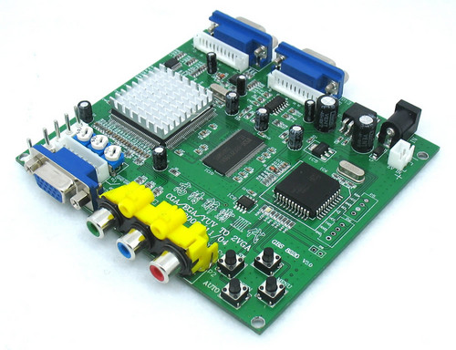
To assist with defining the video signal for optimum display, an easy to use yet comprehensive OSD menu allows all facets of the input signal and the resultant output video image to be adjusted to suit the end users needs. The Auto Scan feature allows for inter-working with Progressive or Interlaced video signals. These connectors will allow video signals from RGBHV, RGBH+V, RGsB and YPbPr video sources to be accepted by the converter and then all output via a standard VGA Dsub-15 pin connector to your monitor. Industrial machines interfacing with the RGB, MDA, CGA, EGA to VGA converter can be connected via 5 BNC input connectors or via a CGA/EGA/VGA Dsub-9 pin input connector. Simply use the converter with any standard CRT or LCD panel that can be purchased in any store. This means that it is no longer so costly to have to repair or replace old screens. With different styles of Industrial machinery, using various combinations of horizontal/vertical frequencies and synchronizations in formats ranging from MDA (single colour) to VGA (multi-colour), the RGB, MDA, CGA, EGA to VGA converter is ideally suited for helping to replace defunct CRT monitors with newer model CRT and LCD screens.

Ega to vga converter circuit full#
The device supports synchronization types of Separate, Combined (Composite) and Sync on Green, as well as full support for Monochrome, Greyscale and Colour analog and digital video formats. The output horizontal resolution is unconstrained and the output vertical resolution is from 200 ~ 600 lines. The converter will auto-scan and accept horizontal scan frequencies from 12kHz ~ 40kHz with the vertical scan frequency unconstrained.
Ega to vga converter circuit Pc#
The RGB, MDA, CGA, EGA to VGA Converter is a new multi-frequency scan converter, up-scaling to PC VGA and SVGA resolutions. You will find a example of the connectivity options here in the how-to's.News | Latest Products | Specials | Stock List | Glossary | Contact Us (Do NOT adjust when the problems are different!)Ĭomes with 2 pin 5V power cable and 8 pin video cable (RGBS). Note that the ST value must be lower than the SP value. If the image colours is blurred or blacked out you can use the "Clamp Clamp ST and SP" setting to adjust. Hold the button "Down / Auto" for 5 seconds.
Ega to vga converter circuit tv#
With this converter board you can convert CGA, EGA or YUV component signals to VGA and display them on a 31kHz PC VGA monitor, LCD display, TFT monitor or HD TV with VGA connection.


 0 kommentar(er)
